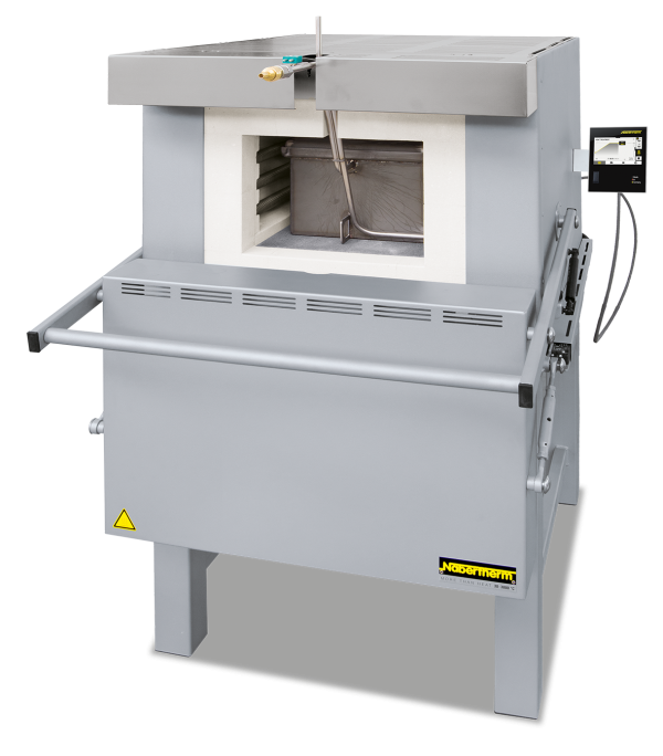
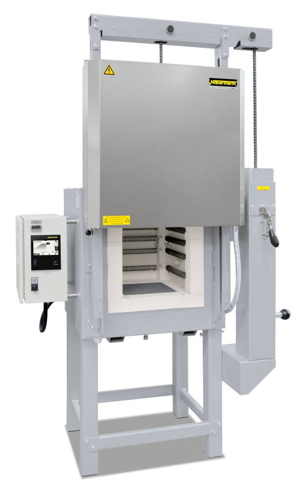
Skrzynki gazowe do modeli N 7/H - N 641/13
Na życzenie mogą zostać zaoferowane próby w naszym centrum testów.

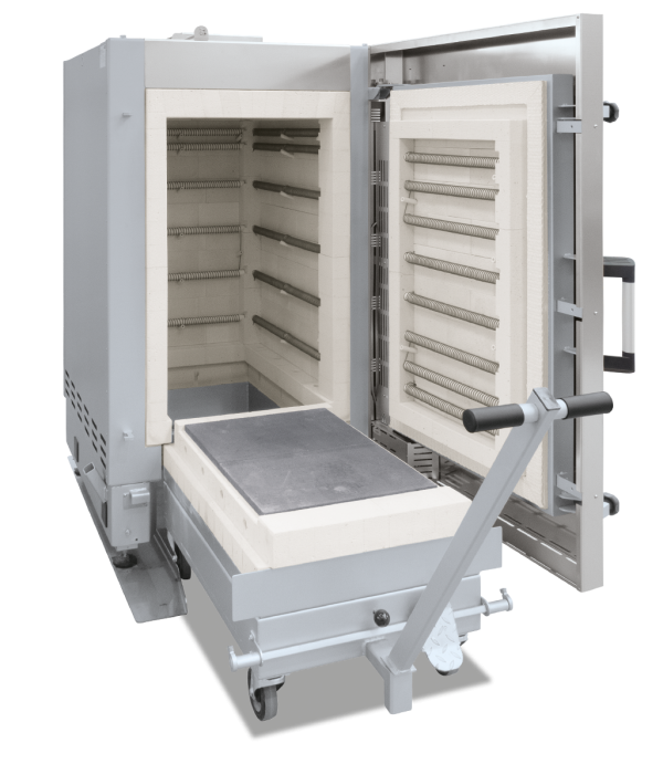
Funkcja i wyposażenie

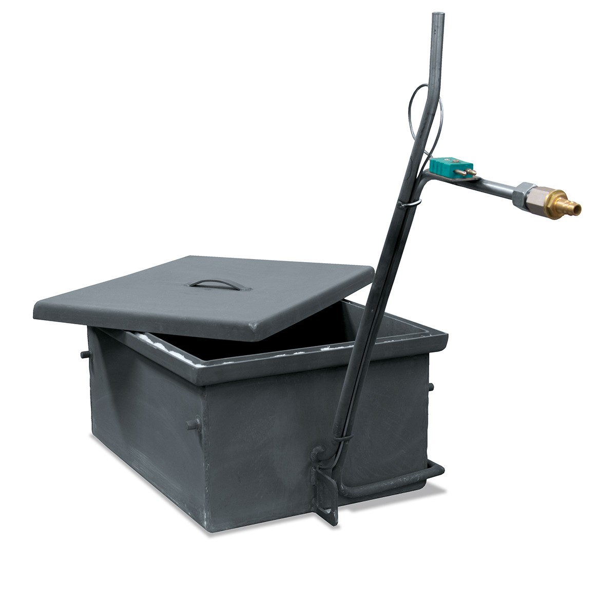

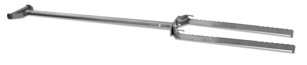
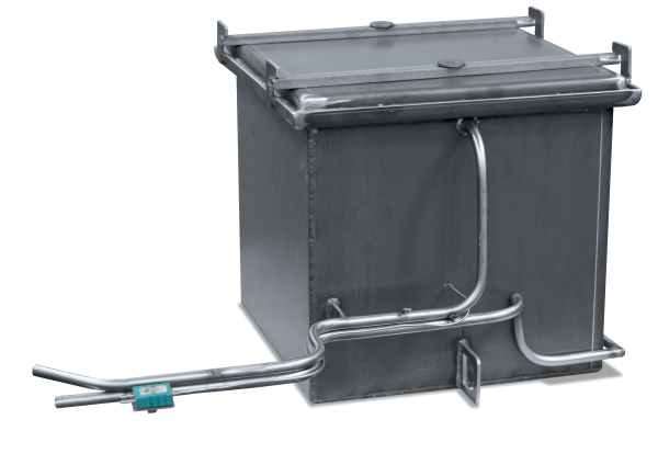
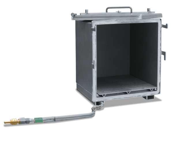
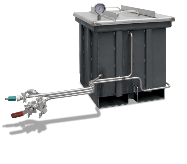
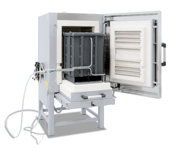
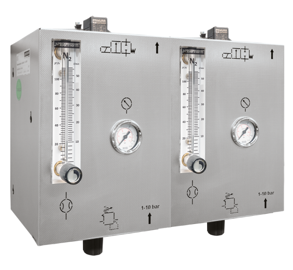
The annealing boxes for heat treatment under protective gas are equipped with a protective gas intlet and outlet. A box with protective gas is advisable for larger workpieces requiring defined heat treating. We would be pleased to carry out Trials at our technical center can be carried out on request. Up to furnace model N 61/H with downward door opening the gas ductway is laid through the upper section of the door collar, for larger furnaces with upward door opening the supply line is laid through the lower furnace collar. The box is pressurized with non flammable protective and reactive gases such as argon, nitrogen or forming gas via the protective gas tube. There are manual and automatic systems available for protective gas. See pages 52 - 53. for more information about protective gases which can be used as well as manual and automatic protective gas systems. After charging the box it is closed and preflushed outside the furnace. Afterwards the box is placed in the preheated furnace. The quantity of gas can be reduced to the process flush quantity. After the heat treatment the box is pulled out of the furnace, the charge taken from the box and placed in the quenching medium. We recommend using binding wire on the parts so that they can easily be grasped by tongs. A flexible type K thermocouple is installed in the box for measuring the temperature; we recommend connecting it to a digital display device or to a temperature recorder. The box can also be cooled down on a cooling platform while closed. Be sure that the protective gas flowrate is increased for this application.
- Tmax 1100 °C
- For non-combustible protective and reactive gases argon, nitrogen and forming gas (observe national regulations)
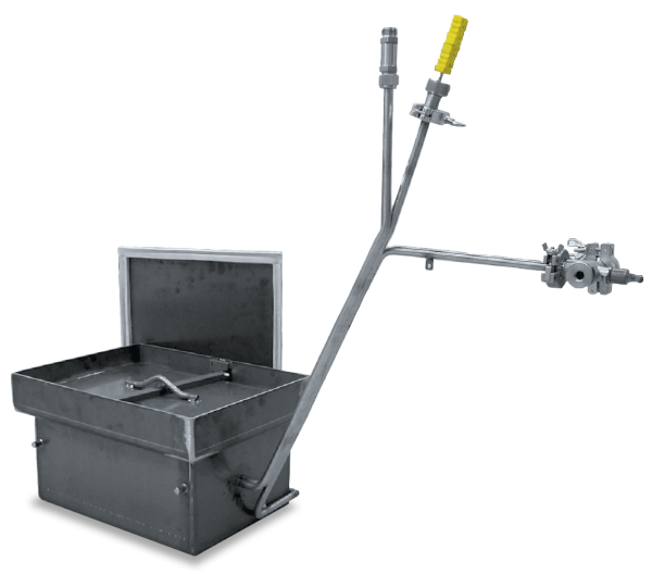
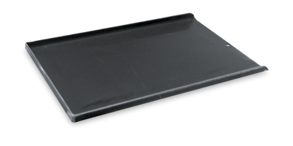
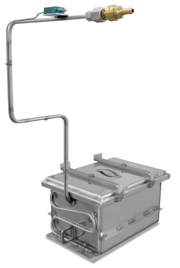
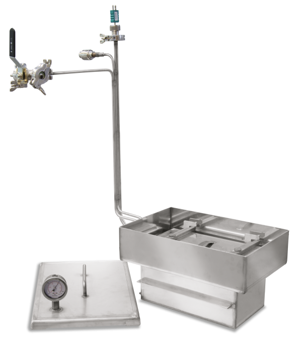
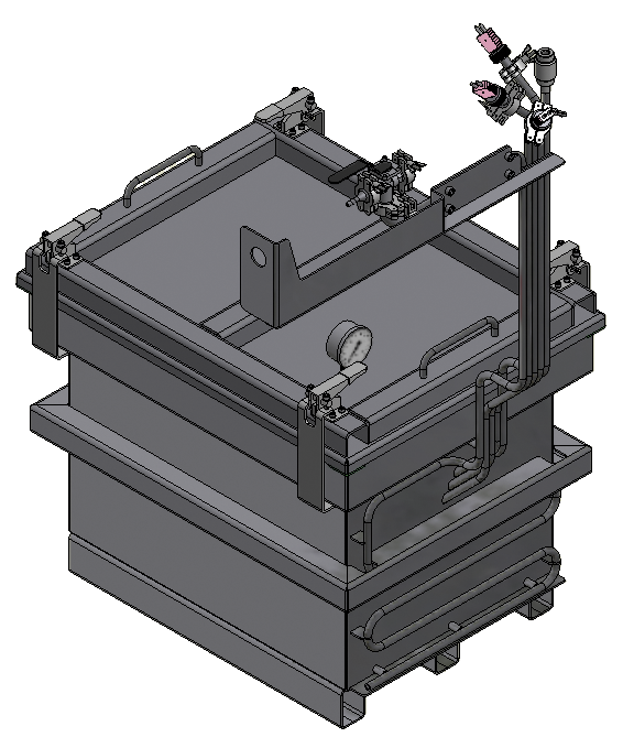
- Protective gas box with fiber sealing and lid, gas supply via a tube into the bottom of the box
- Protective gas connection via quick coupling with hose connector (inner diameter 9 mm)
- Piping for gas inlet and outlet through the furnace collar
- Heat-resistant alloy 314 (AISI)/(DIN material no. 1.4841)
- Charge thermocouple type K for temperature display or charge control
Dalsze produkty
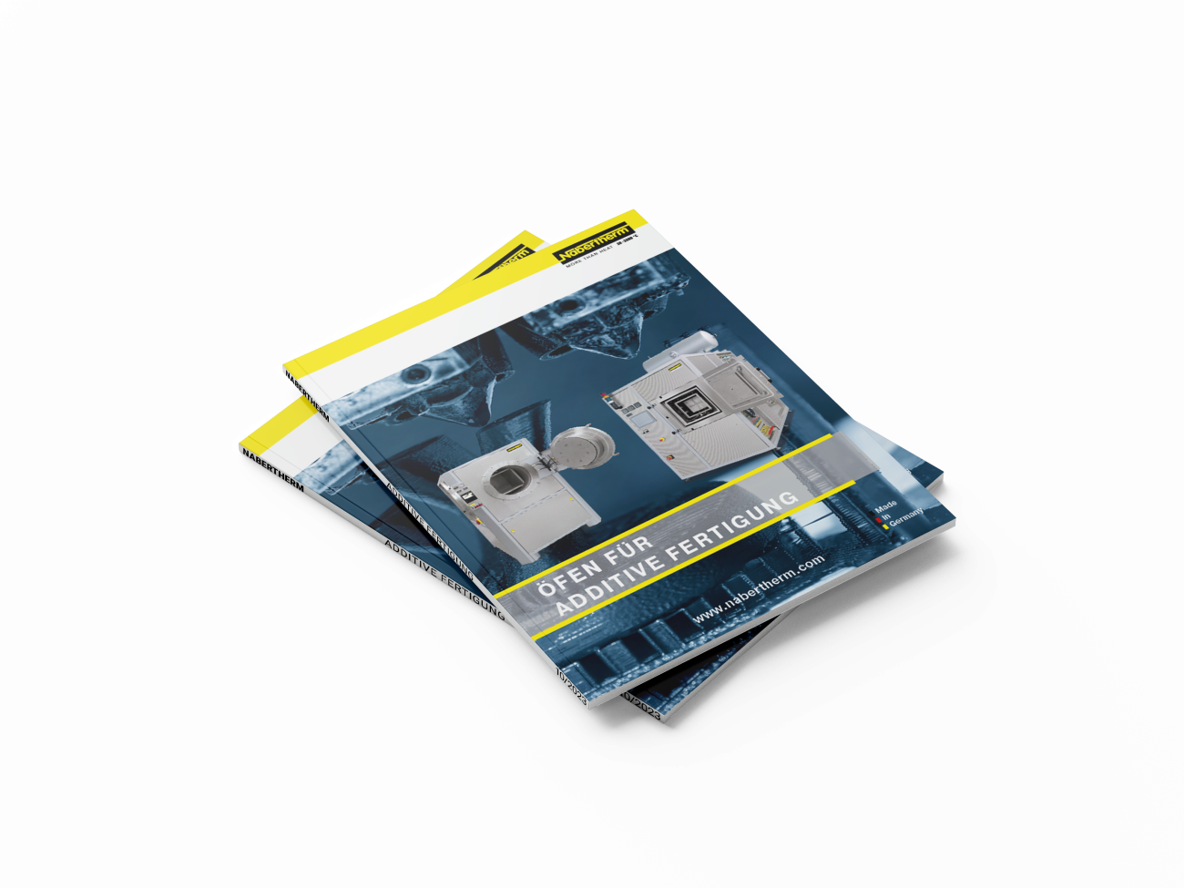
Katalogu
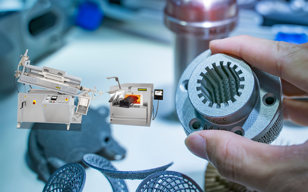
Kompletny przegląd naszej szerokiej oferty pieców do obróbki cieplnej materiałów wytwarzanych metodą 3D można znaleźć w naszym katalogu „Produkcja addytywna”.